What Is a Structural Steel Drawing? A Guide for Contractors and Clients
Understanding Structural Steel Drawings: A Plain-English Guide
If you have ever received a set of structural steel drawings and felt unsure about what you were looking at, you are not alone. Structural steel drawings are highly detailed technical documents that contain a significant amount of information, and for anyone who does not work with them day to day, they can appear complex and difficult to interpret.
Understanding what structural steel drawings contain, how they are produced and how they are used is valuable for anyone involved in procuring, managing or constructing a steel-framed building, from main contractors coordinating a construction programme to clients trying to understand what has been designed for their project.
In this guide, we explain the different types of structural steel drawing, what each one contains, and how they are used through the design, fabrication and construction process.
Why Are Structural Steel Drawings Important?
Structural steel is fabricated off site to precise dimensions before being delivered and erected on site. Unlike some other construction materials that can be cut, adjusted and modified relatively easily on site, structural steelwork must be manufactured accurately to the dimensions shown on the drawings before it leaves the fabrication workshop.
This means that the quality and accuracy of the structural steel drawings have a direct impact on the quality and accuracy of the finished steelwork. Errors, ambiguities or missing information in the drawings can result in components that do not fit correctly on site, requiring costly remedial work, programme delays and, in some cases, the re-fabrication of affected components.
Getting the drawings right, and ensuring that everyone involved in the project understands and works from the correct version of those drawings, is therefore one of the most important aspects of managing a structural steel project successfully.
The Different Types of Structural Steel Drawing
There are several distinct types of drawing involved in a structural steel project, each serving a different purpose and produced at a different stage of the design and construction process.
General Arrangement Drawings
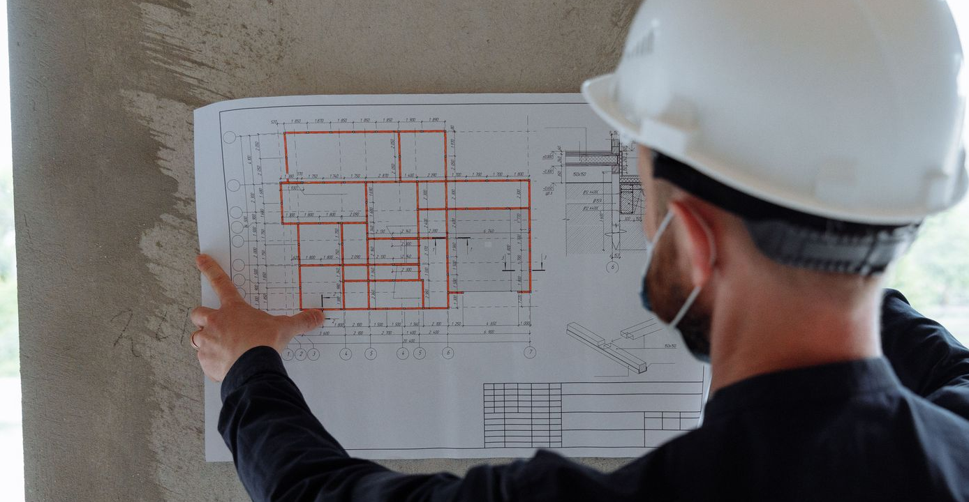
General arrangement drawings, often referred to as GA drawings, are produced by the structural engineer as part of the overall building design. They show the layout and geometry of the structural steel frame in plan, elevation and section, giving an overall picture of how the structure is arranged within the building.
GA drawings typically show the positions of columns, beams and other structural members, the overall dimensions of the frame, floor levels and structural grid references, primary connection points and the relationship between the steel structure and other building elements such as foundations, floors and cladding.
GA drawings are the starting point for the fabrication process. The steel fabricator uses them to understand the overall scope and geometry of the steelwork package before producing more detailed fabrication drawings.
Structural Calculations and the Engineer's Design
Alongside the GA drawings, the structural engineer produces a set of calculations that define the sizes, grades and properties of each steel member required to carry the loads acting on the structure. While the calculations themselves are not drawings, they inform the member sizes shown on the GA drawings and are an essential part of the design package.
The fabricator will typically receive the GA drawings and member schedule rather than the full calculations, but it is worth being aware that every member size and connection detail shown on the drawings has been derived from a set of structural calculations that define its minimum requirements.
Fabrication Drawings
Fabrication drawings are produced by the steel fabricator, based on the structural engineer's GA drawings and specification. They are the detailed working drawings from which the steel components are actually manufactured in the workshop.
Fabrication drawings are far more detailed than GA drawings and contain all of the information needed to fabricate each individual component accurately. This includes the precise dimensions of every member, the exact positions of all holes for bolted connections, the size, type and length of all welds, the grade of steel to be used, the surface preparation and coating requirements and any special fabrication instructions relevant to particular components.
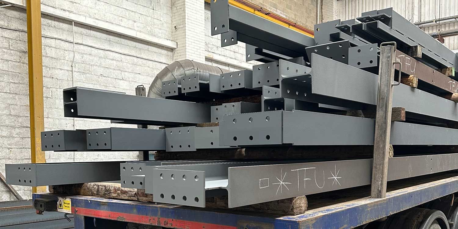
Each fabricated component is typically assigned a unique piece mark, which is a reference number or code used to identify that component throughout the fabrication, delivery and erection process. Piece marks appear on both the fabrication drawings and on the physical steelwork itself, usually marked in paint or chalk, making it straightforward to match components to drawings on site.
Fabrication drawings must be checked and approved by the structural engineer before fabrication begins. This approval process is an important quality assurance step that confirms the fabricator has correctly interpreted the engineer's design intent.
Erection Drawings
Erection drawings are produced alongside or as part of the fabrication drawing package and show how the fabricated components are to be assembled on site. They are the primary reference document for the steelwork erector during the construction phase.
Erection drawings typically show the positions of all columns on the structural grid, the erection sequence for the frame, the location of each fabricated component using its piece mark reference, the positions and details of all on-site connections, and any temporary works or propping required during erection.
A well-prepared set of erection drawings makes the site erection process significantly more efficient and reduces the risk of components being installed in the wrong position or orientation.
Connection Details
Connection details are drawings that show the specific design of the joints between structural members. In some cases these are incorporated into the fabrication drawings, and in others they are produced as separate detail sheets.
Connection details typically show the size and arrangement of bolts, the dimensions and thickness of end plates, cleats and gusset plates, the size and type of welds, and any specific requirements for high-strength or preloaded bolt assemblies.
Connection design is an area of structural engineering that requires particular care, as connections must transfer loads safely between members while also being practical to fabricate and erect. In the UK, connection design is often carried out by the fabricator's own engineering team working within parameters established by the structural engineer, a process known as contractor-designed connections.

Understanding the Information on a Structural Steel Drawing
Even without a background in structural engineering, understanding the key elements of a structural steel drawing helps you engage more effectively with the design and construction process.
The drawing title block
Every structural steel drawing has a title block, usually located in the bottom right-hand corner, which contains key reference information including the project name and address, the drawing title and drawing number, the revision number and date, the scale of the drawing, the name of the company that produced it and the names of the people who drew, checked and approved it.
Always check the revision number and date when working from a drawing to ensure you are using the most current version. Using a superseded drawing is one of the most common causes of fabrication and construction errors.
The structural grid
Most structural steel drawings are referenced to a structural grid, which is a system of numbered and lettered reference lines that define the positions of columns and other structural elements. Grid references allow any point in the structure to be precisely located and described, and they provide a common reference system that is used consistently across all drawings for a project.
Member references and section sizes
Beams, columns and other structural members are typically identified on drawings using a combination of their section designation and their piece mark reference. The section designation describes the type and size of the steel section, for example 305x165x40 UB, which refers to a universal beam 305mm deep, 165mm wide and weighing 40 kilograms per metre.
Understanding section designations is not essential for most contractors and clients, but being able to recognise them on a drawing and understand that they represent a specific, standardised steel section is useful context.
Dimensions and tolerances
Structural steel drawings show dimensions to a high level of precision, typically to the nearest millimetre for overall member lengths and connection details. These dimensions reflect the tight tolerances required in structural steelwork fabrication, which are governed by BS EN 1090 and the relevant product standards.
Revision clouds and revision notes
When a drawing is revised, the changes are typically highlighted using a revision cloud, which is a cloud-shaped outline drawn around the area of the drawing that has changed. A revision note in the title block records what changed, when and why.
Paying attention to revision clouds is important for anyone reviewing updated drawings, as they quickly highlight what has changed between one version and the next without requiring a detailed comparison of the full drawing.
The Drawing Approval Process
Before fabrication can begin, the fabrication drawings must go through a formal approval process. This typically involves the fabricator submitting the drawings to the structural engineer, and in some cases the main contractor and architect, for review and approval.
The reviewing parties check that the fabrication drawings correctly reflect the design intent shown on the GA drawings, that all member sizes and connection details are as specified, and that there are no errors or ambiguities that could result in incorrect fabrication.
Comments and changes are recorded on the drawings and returned to the fabricator, who revises them accordingly before resubmitting. This process continues until the drawings are formally approved, at which point fabrication can proceed.
Delays to the drawing approval process are one of the most common causes of programme slippage on structural steel projects. Establishing a clear approval process with agreed timescales at the outset of a project, and ensuring that the relevant people on all sides prioritise drawing reviews, is one of the most effective ways to protect the fabrication and construction programme.
Working with MAK Structures
At MAK Structures, we work closely with structural engineers, main contractors and clients throughout the drawing production and approval process.
All of our fabrication is carried out in house at our purpose-built 20,000 sq ft facility in Wakefield, West Yorkshire, to UKCA marking requirements up to Execution Class 3.
If you have a project in the pipeline and want to discuss the fabrication drawing process or any aspect of your steel package, our team would be happy to help.